Designed by the California Institute of Technology, a silicon-based optical gyroscope with an area of ​​only 2 square millimeters has benefited from a noise self-cancellation technique that overcomes the major sources of error in such miniature inertial units.
Micro gyroscopes and accelerometers are the basic components of inertial navigation, and these technologies are evolving. Mechanical rotors and laser optical gyroscopes have been replaced by fiber optic gyroscopes and MEMS gyroscopes in many applications, but fiber optic gyroscopes and MEMS gyroscopes are difficult to achieve the accuracy specifications of the former. Efforts to miniaturize fiber optic gyroscopes continue to be frustrated by lower signal-to-noise ratio (SNR) due to size and path length and second and third-order errors due to thermal fluctuations, component drift, and manufacturing mismatch.
Engineers know that by using techniques such as pre- or continuous calibration, inherent errors in the system can be reduced. They minimize the source of error by using better components and materials, and by designing an architecture that can self-offset errors. The latter may be the best possible technology, and a California Institute of Technology research team funded by the Rothenberg Innovation Program designed, built and tested a new solution for a silicon-based micro-optical gyroscope. The cost and negative effects are low and provide accurate performance metrics.
Designed by Caltech, the optical nanogyroscope is only 2mm x 1mm, but has excellent performance due to a technology that eliminates major sources of error.
Their solution leverages its "reciprocity" called passive optical networks to dramatically reduce thermal fluctuations and mismatches, resulting in better results than previous solutions. Their demonstration devices, although 500 times smaller than the most advanced micro-fiber gyroscopes available today, are capable of detecting phase shifts 30 times smaller than the latter, bringing the overall performance of such optical gyros to one to two orders of magnitude.
The research, "Nanophoton Gyroscopes with Reciprocal Sensitivity Enhancement," was published in Nature, and they detailed this approach in the paper, somewhat similar to the use of differential signals to eliminate common-mode electrical signals. Like all optical gyroscopes, their devices use the relativistic Sagnac Effect, which measures two counter-rotating light waves created by a beam splitter from a single source (one as a reference path and the other as a signal path). The relative phase shift between them to determine the angular velocity. According to the Sagnac effect, the two counter-rotating light waves meet in the opposite direction in the same loop for one week, and then interfere on the screen. When there is a rotational angular velocity in the loop plane, the interference on the screen The fringes will move, and the number of fringe movements in the Sagnac effect is proportional to the product of the angular velocity of the interferometer and the area enclosed by the loop.
The overall performance of such an optical gyroscope is often closely related to the path length, with longer paths providing higher accuracy and slightly less sensitivity to dynamic differences between the two paths. Minimizing the path by integrating the optical waveguide in the silicon substrate, rather than through the fiber length or vacuum path, means that the sensitivity is improved for any path-related changes.
Optical gyro and Sagnac effect: a silicon-based nanophotonic waveguide supports a single mode waveguide (a) at 1550 nm; the rotation of the ring causes a phase difference between two counter-rotating waves (b); In sensitivity enhancement techniques, the input signal switches between a red path (clockwise propagation) and a blue path (counterclockwise propagation).
To solve this problem, the Caltech team used a device design that continually alternates the optical path at any rate above any fluctuation (as shown above). The "polarity" of the signal passing through the silicon optical waveguide is reversed, and common mode components such as thermal fluctuations and mismatches are eliminated. In this case, "reciprocity" means that both beams in the gyroscope optical waveguide are affected by the error in the same way.
Of course, its overall design uses a range of electronics, including a pair of channels consisting of a photodiode, a transimpedance amplifier (TIA), and a variable gain amplifier (VGA), as well as a low-pass filter and demodulation (as shown below). ).
The figure above shows: an input Mach-Zehnder interferometer for path switching (a); an implementation of a nano-optical gyroscope schematic (b); each optical signal is captured by a photodiode and is used by the TIA and VGA signal chain Amplify, then add and multiply the reference frequency by the passive mixer to extract the amplitude information (c) of the encoded rotation rate.
The fully integrated optical gyroscope, led by research team led by Ali Hanjimi, Professor of Electrical Engineering and Medical Engineering at the California Institute of Technology, is only 2mm x 1mm. The team believes that their reciprocity sensitivity enhancement scheme has greater advantages than solutions that use incoherent sources or low-loss waveguides, which typically require different, more difficult to fabricate optical waveguide cores and cladding materials. Lower complexity. In addition, it is capable of detecting the smallest recorded phase shift (only 3 nanoradians) in all miniaturization schemes achieved so far in silicon-based nanophotonics.
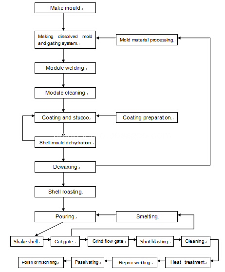
Investment casting technical flow process

The silica sol casting process also called precision investment casting process. It is a less cutting or no cutting casting process. It is an excellent technique in foundry industry. Its application is very extensive. It not only applicable to various types, various kinds of alloy and casting, and produce the casting dimension accuracy and surface quality is higher than other casting method, Even other casting method can not do the complex, high temperature resistant, not easy machining castings, all can be used for investment precision casting process.
The investment casting process, it is a process that use fusible materials make soluble model, and coated with several layers of tailor-made refractory coating on the surface, after drying and hardening become a whole shell, melt the shell model by steam or hot water. Then put the shells in the sand, filling dry sand in all round and modeling. Finally roasting it based on high-temperature in the furnace, the shell after roasting, and getting the casting part after pouring molten metal.
The investment casting process can produce High precision dimensional parts, generally can reach to CT4-6(sand casting is CT10-13, die casting is CT5-7). Due to the complexity of investment casting process, there are many factors influencing the casting dimension accuracy. Such as shrinkage of mold material, deformation of the casting, Shell heating and cooling line quantity change in the process, alloy shrinkage and deformation of castings in the solidification process. The surface finish of investment castings is higher than the ordinary casting, can reach to Ra1.6~3.2.
The greatest advantages of investment casting is casting parts have high dimensional accuracy and surface finish, so it can reduce the mechanical processing. The another advantage of investment casting method is that it can cast all kinds of alloy and complex casting part, special casting high temperature alloy casting part.
The precision of the Steel Casting Part: ±0.15mm~
Smoothness of surface of rough part: Ra6.4;
Shrinkage rate of steel investment casting products: 0.6%;
Material wastage rate: 5%;
General stainless steel casting part machining allowance: 0.7mm;
Surface preparation methods: Sand blasted, Shot blasting, Powder coating, Painting, Plating, Electrophoresis, Polishing.
Our company's production equipment and management system
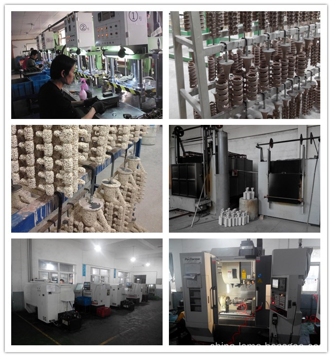
CNC machining center: 8 sets AIGEMA A-8;
CNC lathe machine: 6 Guangzhou Machines and 7 Shenyang Machines;
Work days of one week: From Monday to Saturday;
Shift work: 2 shift per day;
Working hours: From AM 8:00 to PM 5:00;
2D and 3D drawing Software: AutoCAD, UG, Pro/E, SolidWorks 2013;
QC control: New type NANO CMM, FPI M5000 desktop metal analyzer, Easson projector, Mechanical properties tester.
The steel casting process and machining equipment:

Steel Casting Part
Stainless Steel Lost Wax Casting, Steel Casting Part, Steel Investment Casting Part, Steel Silica Sol Casting Part
NINGBO BEILUN LEMA MACHINERY TECHNOLOGY CO.,LTD , http://www.china-lema.com