1 Introduction
The hydraulic pumps used in the positive displacement hydraulic transmission mainly include gear pump, vane pump and piston pump. Among them, the gear pump is the simplest structure, and it has a small size and a small number of parts (especially the requirements High-precision processing of parts, light weight, easy manufacturing and maintenance, low price, even in poor working conditions can work reliably, so in the hydraulic transmission and control technology and in all types of hydraulic machinery and petrochemical industry Fluids are used in a wide range of applications. Until now, the vane pump and the plunger pump can all be made into variable pumps in various forms. Only the gear pump has so far been available. Exploring the variable mode of the gear pump has great practical significance for expanding the field of use of the gear pump. This article describes several ways to solve the gear pump variables, which can provide references for the research and development of variable gear pumps.
2 Ways of Gear Pumps to Achieve Variables
2.1 Variable-level variables (1) Two-gear type As we all know, the conventional two-gear type gear pump uses two involute gears with the same parameters (ie, the two gears are exactly the same size and size). The number of teeth of the two gears (the other parameters of the gears are unchanged) make the two gears different in size (Figure 1). The gear pump thus constructed can obtain two kinds of output displacement. In the case of the same rotational speed of the prime mover, if the pinion gear is used as the driving wheel, the displacement and flow rate of the gear pump output is small; and if the large gear is used as the driving wheel, the gear pump can output a larger displacement. In this way, a gear pump can provide two kinds of displacement. According to the calculation formula of the displacement of the gear pump, the ratio of these two displacements is equal to the ratio of the number of teeth of the large and small gears (in a positive ratio relationship). This concept has certain practical significance for hydraulic equipment that requires two kinds of flow, but The gear pump drive system is more complex than conventional gear pumps.

Figure 1 Gear pump consisting of two different gears
(2) Multi-gear type uses three or more gears to form a multi-gear type gear pump. The driven gear is evenly distributed around the driving gear (Figure 2). This type of gear pump can achieve various displacements. Each displacement can be diverted and output to drive different actuators separately, and can also output a large displacement to achieve rapid movement of the working mechanism. Several corresponding oil inlets and oil outlets are opened on the casing or the front and rear ends of the pump, which are respectively connected with the oil suction pipe and the oil drain pipe. In addition to obtaining a variety of output displacements, this multi-gear type gear pump has another significant advantage: Since the suction and discharge ports are arranged symmetrically and the driven gears are evenly distributed, hydraulic pressure and meshing force are balanced. This reduces the load on the pump shaft and bearings and improves the service life of the gear pump. However, the oil pumping device of this gear pump is more complicated than the conventional two-gear type gear pump, especially the design and processing of the internal gear in the gear pump with internal gear is difficult, and these problems still need to be further studied.

Figure 2 Multi-gear gear pump
2.2 Infinitely Variable Methods (1) With inner ring gear The former Soviet Union had developed a gear pump with uniform variation. The driving gear 1 meshed with the middle gear 2 (ring gear with ring gear) and the driven wheel 3 With the 2 ring gear mesh (Figure 3). The position of the wheel axis of the gear 3 is adjustable, and the axis position (planar motion) of the gear 3 is adjusted so that the output displacement of the pump can be evenly changed between qmin and qmax (corresponding to the movement of the driven gear from the dotted line position to the solid line position, The symbol q represents the displacement of the pump). However, the intermediate gear 2 needs to process both external teeth and internal teeth, which is difficult to process. Moreover, a radial through hole needs to be opened in the root portion of the gear 2, which weakens the strength of the gear.

Fig. 3 The uniform variable gear pump
(2) Rotating sleeve type We know that the angle between the transitional seal area between the high and low pressure chambers on the inner surface of the casing of a conventional two-gear type gear pump is φ ≥ 360°/z (z is the number of teeth of a single gear). . Relevant literature proposes a new concept of changing the angle of the sealing zone: using a rotatable sleeve (with a shunt slot on it), and/or changing the angle of the transitional sealing zone by means of rotation of the sleeve (such that φ<360o/z ), so that part of the high-pressure oil back to the suction chamber according to a certain law, so as to achieve a stepless change in the output flow of the pump, and the outlet flow of the pump is proportional to the rotation angle of the rotating sleeve.
(3) The variable mesh length is calculated from the output displacement of the involute gear pump with outer mesh: q=2πKzLm2 (where z and m are the number of teeth and modulus of the gear, and L is the meshing of the tooth width in the gear). Length, L=B, B is gear width, K is compensation coefficient, K=1.06 to 1.115), displacement q is proportional to z, L, and m2. For gears that have been machined, the number of teeth and modulus are determined. Therefore, by changing the engagement length L, the output displacement of the gear pump can be changed. Specifically, the axial meshing length of the two gears can be changed by manually or automatically moving the position of the driven gear, thereby achieving a linear change in the output flow rate of the gear pump. . Obviously, the maximum meshing length Lmax=B, and the minimum meshing length is limited by the volumetric efficiency of the pump and the strength and stiffness of the gears, generally Lmin≥B/3, so the ratio between the maximum displacement and the minimum displacement can reach qmax/qmin=3.
(4) Changing the position of the axis The geometric center of each gear of a conventional gear pump coincides with its center of rotation. The related literature describes an external gear pump with eccentrically supported gear pairs, that is, the geometric center of the gear and its rotation center are not Coincidence, there is an eccentricity between the two. In this way, a crescent-shaped volume is formed between the gear tip circle and the inner wall of the pump body (see Figure 4). When the left gear rotates 180o, this crescent-shaped volume appears on the right gear. Therefore, compared with the conventional gear pump, in the case of the same size of the gear, it outputs two more crescent-shaped volumes per revolution than the conventional gear pump (generally 40% to 60% more output). However, the eccentricity of the eccentric pump is fixed in the text, and the position of the rotating shaft is also fixed, so the output flow is constant, that is, it belongs to the quantitative pump category. Inspired by this article, the author conceives that if a mechanism is specifically designed so that the eccentricity between the axis of the rotating shaft and the geometric center of the gear can be adjusted within a certain range, the output displacement of the eccentric pump can be changed and it becomes a variable gear. Pump. Of course, there is a lot of work to be done in the parameter design of the variable eccentric gear pump, the sealing of the oil suction and discharge chamber, noise, and unloading.

Figure 4 eccentric gear pump
(5) variable speed In view of the ultimate purpose of the gear pump variable is to achieve a variety of fuel flow output, according to the output flow of the hydraulic pump Q = qn.ηv (q is the displacement, n is the rotational speed of the drive, ηv for the pump Volumetric efficiency) It can be seen that by increasing or decreasing the rotational speed, the output flow of the gear pump can be changed. However, in addition to the limitation of the structure of the parts, the increase in the speed must be prevented by increasing the centrifugal force of the oil when the speed is increased. The oil cannot enter the suction port or fill the entire tooth space due to the increase of the centrifugal force. Air, cavitation phenomenon. The maximum allowable speed is related to the viscosity of the working fluid. Generally, the maximum speed is determined by limiting the peripheral speed of the gear top circle. Likewise, the gear pump speed must not be too low, as the leakage loss increases as the speed decreases. When the speed is low until the amount of oil discharged is equal to the amount of leakage, the gear pump cannot discharge oil at all. Under normal circumstances, the actual gear pump speed can not be less than 300r/min. Since the gear pump is generally driven by the motor, under the premise of considering the above-mentioned speed limit condition, if the frequency conversion stepless speed control method is used to control the speed of the conventional gear pump, the drive motor may be changed according to the actual required flow rate. The rotational speed of the pump not only achieves the requirement of variable output flow, but also saves energy and improves the overall operating efficiency. Variable frequency speed control is one of the ten major high-tech technologies that China has focused on. To install a frequency converter on the drive system of traditional gear pumps is a new and effective way to achieve variable flow output of gear pumps.
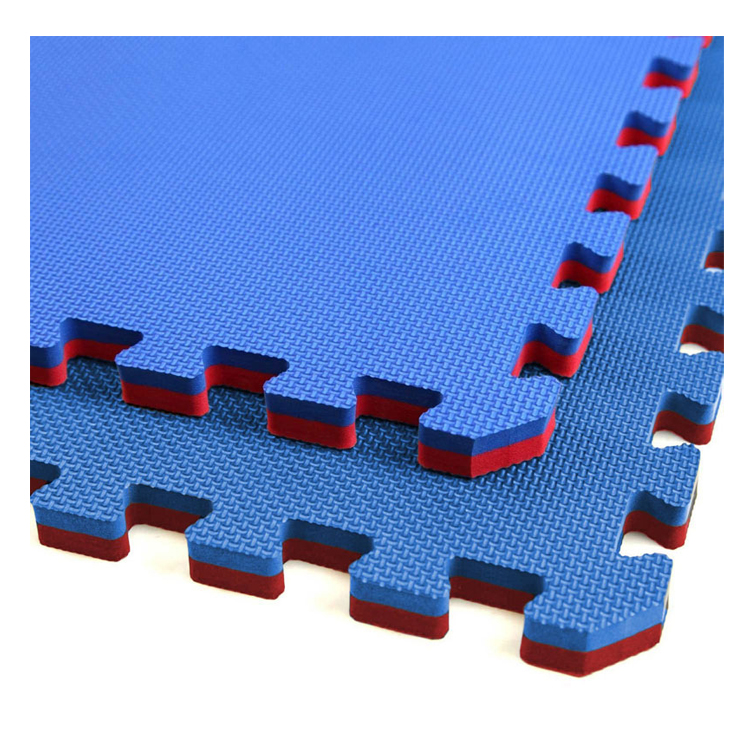
Martial Arts Mat is an EVA Mat, in double colors for reversible, in 100cm x 100cm, offering 2cm, 2.5cm, 3cm and 4cm thickness.
EVA martial arts mat is made from Eco-friendly, high density, closed cell, non-smell and non-toxic EVA foam material. With interlocking edges, each mat can be connected easily without any loose.
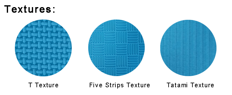
It is always used as EVA Tatami Mat, EVA Jigsaw Mat, EVA Taekwondo Mat, EVA Karate Mat, EVA Judo Mat, EVA Jiu Jitsu Mat and EVA Aikido Mat. The thick foam provides a protection for trainers when they fall on the floor. Also we have 3 different textures for surface of the mats, which is "T" texture, five strips texture and tatami texture. All of them provide a good traction to the feet.

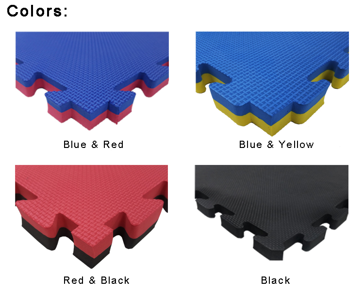
The colors we usually offer for the martial arts mat is blue & red, blue & yellow, black & red, single black. Or we can offer customized colors based on customers` requirement.


We used heard many of customers complained about the bad experience on the bad smell mats they purchased from other supplier. Indeed, that may cost a lower even half of our price, it is because the EVA foam material is what we call second-hand material, its smell will make people uncomfortable. Melors promise that the EVA foam material we use would be never second-hand foam material, what we offer is truly non-smell and non-toxic.
Martial Arts Mat,Eva Martial Arts Mat,Eva Taekwondo Mat,Interlocking Jigsaw Mat,Tatami Interlocking Mat,Eva Karate Mat
Huizhou City Melors Plastic Products Co., Limited , https://www.evaexpert.com