Fig. 1 Gas Door Compound Angle File
 i (see Figure 3), there are:
  i=[ xni ]=[ cosgoisinbHi ] yni cosgoicosbHi zni singoi (1)
Fig. 2 Machine coordinate system and tool grinding initial position type goi is the direction complementary angle of the tool surface i normal vector (the angle with the XOY coordinate plane); bHi is the projection of the tool surface i normal vector on the XOY coordinate plane. Y axis angle. If a bowl-shaped grinding wheel is used (Fig. 2b) and the working plane of the grinding wheel is perpendicular to the Y-axis, then the sharpening face i should have its normal vector coincide with the opposite direction of the Y-axis. For this purpose, the following two rotations can be performed from the position of Figure 2b: The tool is rotated around its own axis (X-axis at this time) to the wd angle, so that the normal vector of the blade surface i is transferred to the XOY plane (the fourth quadrant). Obviously There are: wd=-arctan( zni ) yni (2)
After this rotation,
 i go to
  'i's location:
  'i=[ x'ni ]=[ xni ] y'ni ynicoswdi-znisinwdi z'ni ynisinwdi+znicoswdi (3)
Figure 3 Knife Face Vector
 1=[ 0.499 ];wd1=3.463°;
  '1=[ 0.499 ];wc1=-29.955° -0.865 -0.866 0.053 0 Similarly, find the angles wd and wc at which the other surfaces change from the sharpening start position (the position shown in Figure 2b) to the sharpening position. The space coordinate calculation takes a point P on the blade surface, and its vector representation is:
  p=[ xp
 Yp
Zp ] P point and tool together around their own axis (Fig. 2b position X axis) turn wd angle
 p becomes
  P1:
P1:  P1=[ xp1 ]=[ xp ] yp1 ypcoswd-zpsinwd zp1 ypsinwd+zpcoswd (5)
  P1 turns to wd angle around Z axis and becomes
  P2:
P2:  P2=[ xp2 ]=[ xp1coswc-yp1sinwc ] yp2 xp1sinwc+yp1coswc zp2 zp1 (6) For example, the vector of the point P1 on blade 1 in the position shown in FIG. 2b is:
  p=[ 56.440
 -11.751
0 ] Rotate wd1 around its own axis (X axis), then rotate wc1 around Z axis to get:
 P2=[ 43.044
 -38.344
-0.710 ] The movement amount of each axis of the machine tool face i is moved from the initial position of sharpening to the sharpening position. The amount of movement of each coordinate axis is as follows: { Dxi=xPR-xpi2
Dyi=yPR-ypi2
Dxi=zPR-zpi2
Ddi=wddi
Dci=wcdi (7) where xPR, yPR, and zPR are the coordinates of the reference point on the grinding wheel in the initial position of the sharpening, and xpi2, ypi2, and zpi2 are the cutting positions on the blade surface i from the initial position of the sharpening by the axis around itself (X-axis). ) Rotate the wdi angle and rotate the z coordinate around the wci angle. Equation (7) can be understood as a spatial composite angle tool sharpening movement model. Third, the compound angle boring knife grinding actual grinding, we must first determine the initial position of the tool and the grinding wheel. The determination of the initial position should take into account the ease of tool setting and adjustment, and should prevent the interference of the grinding wheel with the workpiece spindle or non-grinding part of the tool during sharpening. Fig. 2b is a feasible scheme. In the initial position, the axis of the grinding wheel coincides with the Y axis of the machine tool. The grinding wheel working surface is aligned with the guide strip of the tool. The workpiece spindle (tool axis) coincides with the X axis, and the blade surface V is in the horizontal position. And make the f30.938 section of the tool from the origin of the coordinates to a certain value (in this case, set to 50, this value can be obtained by the knife on the first surface). Select the reference point of the grinding wheel according to the size of the grinding wheel. The reference point in this example is: Rw=[ 48
-22.5
0 ] Note: The original parameters of III and IV flank in the table are parameters rotated by 90° about the axis of the tool. Parameters of each flank surface Raw parameters and grinding parameters Table Item I II III IV Raw parameter g0 (face method The angle between the vector and the XOY plane) (°) 3 15 3 15 bH (the angle between the projection of the blade surface vector on the XOY plane and the Y-axis) (°) 150 150 110 110 x0 (the x coordinate of the cutter point on the blade surface) (mm ) 56.44 56.44 52 52 y0(y-coordinate on knife surface) (mm) -11.751 -11.721 -9.974 -9.897 z0(z coordinate on knife surface) (mm) 0 0.5 0 0.5 Sharpening parameter wd ( Rotation around the X axis) (°) 3.463 17.192 8.712 38.076 wc (rotation around the Z axis) (°) -29.955 -28.879 -67.785 -65.186 Dx (X axis compensation amount) (mm) 4.956 4.058 39.284 33.529 Dy (Y axis compensation amount (mm) 15.844 14.692 29.704 28.098 Dz (Z-axis compensation amount) (mm) 0.71 2.987 1.511 5.71 Select P1, P2, P3, and P4 points on the I, II, III, and IV planes respectively (Fig. 2) The calculations are performed, and the original data and calculation results are listed in the right table. If you sharpen the I surface first, move the machine coordinates according to the grinding parameters of the first column in the table, and adjust the small carriage to make the I surface contact with the grinding wheel working surface. At this time, the distance between the section of the tool f30.938 and the origin of the coordinate is 50mm. determine. After proper feeding, feeding in a certain distance in the X direction can complete the sharpening of the I surface. The subsequent sharpening of the II, III, and IV faces does not have to return to the initial position. Instead, the position of each axis of the machine tool can be adjusted according to the difference between the sharpening parameters of the respective blade surfaces, and the sharpening of each blade surface can be realized. Of course, in the actual sharpening process, it is necessary to arrange operations such as knife and indexing. IV. CONCLUSION In this paper, the principle and method of the spatial compound angle boring tool CNC grinding are described by taking the gas door boring reamer as an example. This method is also applicable to the numerical control sharpening of other space compound angle tools. The core of the method described in this paper is to use the vector method to calculate the amount of movement of the required sharpened blade surface from the initial position of the sharpening to the actual sharpening position of each axis of the machine tool. According to this amount of movement, the numerical control machining program can be programmed to realize the spatial compound angle cutter. CNC sharpening. According to the above principles and methods, the precision rotary table and the dividing head can be arranged on a common tool grinder, and the grinding of the space composite angle tool can also be realized.
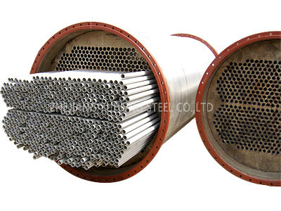
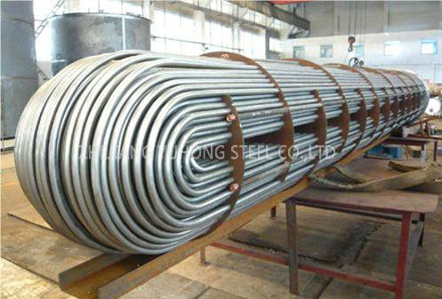
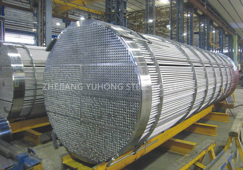
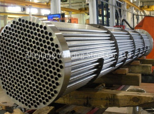
Heat exchanger Tube
Heat exchanger Tube are used in all types of process industries. We offer the market`s widest selection of stainless steel grades and has extensive experience of manufacturing heat exchanger tubes.
Description: Heat-exchanger equipment, pipelines and pipeline components
OD: 15.88, 19.05, 25.4, 31.75, 38.1mm etc;
WT: 1.24, 1.65, 2.11, 2.77, 3.05mm etc;
Main Testing Terms Accoring to ASTM A213 and ASTM A1016, EN 10216-5
1. High pressure hydraulic Test / Hydrostatic testing; 2. Eddy current test, Ultrasonic Test; 3. Mechanical Test, Physical properties test; 4. OD , WT, Length tolerance Test.; 5. PMI Test
Tubes End: The tubes are supplied plain, square cut and on request, the tubes will be deburred.
Application:
Nuclear Industry; Chemical Industry; Petrochemical industry; HVAC (Heating Ventilation Air Conditioning), refrigeration; Food and Beverages; Power Generation


Heat Exchange Tube,Incoloy Heat Exchanger Tube,Inconel Heat Exchanger Tube
YUHONG GROUP CO.,LIMITED , https://www.jessro-pipefittings.com