Audio patch panels are indispensable in professional audio systems. Whether it is a studio or a sound reinforcement system, after the audio patch panel, the entire signal flow will become clear and clear, and the wiring system is clean and tidy. easily.
First, the audio jumper connection function
The audio patch panel has two upper and lower rows of connected devices. The upper row of devices are typically used for signal output (eg, the output of a mixer or the output of other audio devices), and the lower row of devices are typically used for signal input (eg, mixers) Input or input from other audio devices, as shown below:

The figure clearly tells us that there are 48 outputs in the upper row and 48 corresponding inputs in the lower row.
In the above, we will give an overview of the function and structure of the audio patch panel. Below, I will explain the three connection methods commonly used in the audio patch panel.
Second, the three connection methods commonly used in audio patch panels
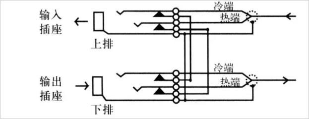
1, Full Normalled (full loop through mode)
The connection method is a serial structure in which the upper row (output) and the lower row (input) of the audio patch panel are internally connected when no jumper plug is inserted. When the jumper plug is inserted into the upper row, the signal output is obtained, and the audio patch panel is internally disconnected from the lower jumper socket. The signal can be input by plugging the jumper plug into the lower socket. At this time, the signal will not be connected to the upper socket. As shown below:

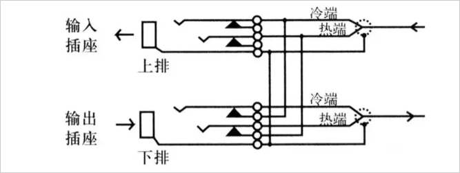
2, Half Normalled (half loop mode)
The connection mode is a parallel structure, and when no jumper plug is inserted, the upper row (output) and the lower row (input) of the audio patch panel are internally connected. When the jumper plug is inserted into the upper row of sockets, the signal output is obtained and the signal is also connected to the lower jumper socket. The signal can now be obtained in parallel by the upper and lower sockets. Connect the dummy plug to the lower socket to prevent the signal from being connected to the lower socket. The signal can be input by plugging the jumper plug into the lower socket. This is, the signal will not be connected to the upper socket. As shown below:

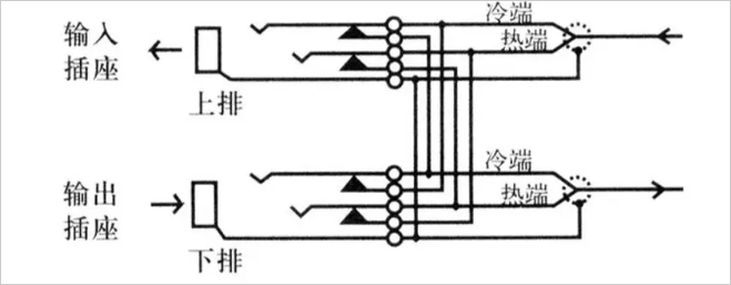
3, double loop through (serial-parallel way)
When no jumper plug is inserted, the upper row (output) and the lower row (input) of the audio patch panel are internally connected. When the jumper plug is connected to the upper row of sockets, the signal output can be obtained, and the signal is also connected to the lower jumper socket. The signal can now be obtained in parallel by the upper and lower sockets. Connect the dummy plug to the lower socket to prevent the signal from being connected to the lower socket. When another jumper plug is plugged into the lower socket, a signal can be input. Please note that the signal is now connected to the upper socket at the same time. To prevent this from happening, you can connect a dummy plug to the upper socket, as shown below:
Cabinet wiring effect after using the audio patch panel correctly
The following photos are the cabinet wiring effects after the correct use of the audio patch panel. Through this figure, we can clearly see that the whole system is clear and clear, the wiring system is clean and tidy, and the system maintenance is convenient! !
Cabinet without audio patch panel system
The above photo shows the installation cabinet without the audio patch panel. Compared with the above figure, it is obvious that the cabinet is disorderly and there is no obvious idea. Maintenance will become very troublesome! !
supplement:
Marking the line head is definitely necessary. Regardless of the scheme of not using the audio patch panel, as for the interference problem, you can rest assured that this kind of integrated wiring scheme makes a strict distinction between strong and weak electricity, so it will not Interference occurred.
There are several reasons for interference or noise:
1. The system is not strictly grounded according to the standard;
2. The quality of the audio cable is too poor;
3, using unbalanced wiring or wrong production of wire;
4. The installation distance between the strong and the weak electricity is too long.
These four points are the main factors that cause interference and noise, rather than the excessive binding of audio cables.
The Wooden Series offers a diverse range of products that showcase the beauty and versatility of wood. Here are some of the main categories within the Wooden Series:
Computer Cnc Beam Saw,Hinge Boring Machine,Hinge Drill Press,Wood Saw Machine
Captain intelligent equipment co., ltd , https://www.2captain.com